Steel Hub

Wall thickness is not a standalone strength rating for a steel tube. A thicker wall can raise axial, bending, torsional, and connection capacity, but the governing limit state may still be global buckling, local wall buckling, deflection, weld detailing, or the capacity of the joint rather than the member itself. The right thickness is therefore the one that satisfies the controlling design checks for the complete frame, with enough manufacturing tolerance and corrosion allowance for the intended service environment.
For load-bearing frames, the most costly errors occur at both extremes. A wall that is too thin may appear acceptable when only gross section area is reviewed, yet fail compression classification, dent easily during handling, or provide inadequate material for bolted and welded connections. A wall that is unnecessarily heavy can increase steel weight, transport cost, welding heat input, and frame self-weight without improving the governing mode of failure. Selection begins with the structural demand, not with a preferred nominal tube size.
Start with the load path, not the tube catalogue
A steel tube in a frame may act as a column, beam, brace, truss chord, portal-frame rafter, equipment support, or a member carrying combined forces. Each role produces a different relationship between wall thickness and capacity.
Columns are commonly governed by compression buckling. Beams and rafters may be governed by bending resistance, deflection, or local buckling of the compression wall. Braces require checks for tension and compression because a diagonal that performs well in tension can be limited by buckling under load reversal. Members close to connections can experience concentrated bearing, shear, and local yielding that are not visible in a simple member-capacity calculation.
The load model must include more than the obvious permanent weight. Depending on the frame’s location and duty, relevant actions may include imposed loads, wind, snow, seismic effects, crane or machinery actions, impact, thermal movement, vibration, erection loads, and accidental combinations. Load combinations and resistance factors must follow the governing project code. A thickness selected from an allowable working load without checking the applicable combination rules can be materially wrong even when the nominal load appears conservative.
The decisive question is: what force and moment reach this member, at what points, and under which load combination? Until that is defined, comparing tube wall thicknesses has limited engineering value.
Wall thickness changes section properties, but diameter or depth matters too
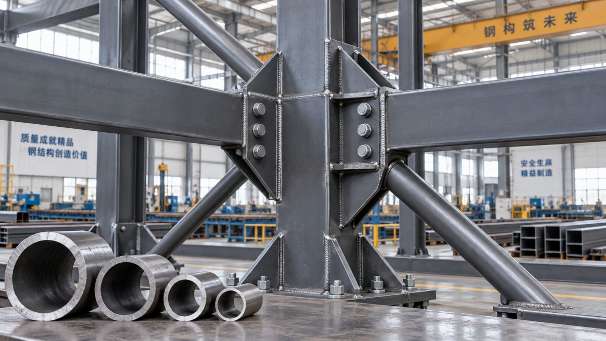
For circular hollow sections, the fundamental dimensions are outside diameter D and wall thickness t. For square or rectangular hollow sections, they are outside width B, outside depth H, wall thickness t, and the corner geometry specified by the relevant product standard. The inside dimensions are reduced by twice the wall thickness.
For a circular tube, the gross cross-sectional area is:
A = π/4 [D² − (D − 2t)²]
Its second moment of area is:
I = π/64 [D⁴ − (D − 2t)⁴]
Area is important for axial tension and short-column compression. The second moment of area, together with section modulus, influences bending stiffness and bending resistance. A useful implication follows: increasing outside dimensions can improve bending stiffness much more efficiently than simply increasing wall thickness, provided local buckling and connection requirements remain satisfactory.
For example, replacing a small, thick tube with a larger, thinner one may provide higher bending stiffness at a similar weight. That does not make the larger thin-wall option automatically better. Its plate elements may be more slender, its connection face may deform more readily, and it may be unsuitable for a connection requiring substantial local bearing or weld capacity. The optimum section balances overall geometry and thickness rather than treating thickness as the sole variable.
Compression members require two separate buckling judgments
Compression design is where nominal wall thickness is most often misread. A tube column must resist both global member buckling and local buckling of its wall.
Global buckling depends on member length, end restraint, frame sway behavior, radius of gyration, steel grade, and the design method in use. A member with a generous wall can still buckle globally if it is long and lightly restrained. The relevant slenderness is based on effective length rather than physical length alone. A pin-ended isolated column, a fixed-base cantilever, and a column in a braced frame do not have the same effective buckling length.
Local buckling occurs when the tube wall plate buckles before the steel reaches its expected yield capacity. This is controlled by width-to-thickness or diameter-to-thickness ratios, often expressed as D/t for circular sections and flat-width-to-thickness ratios for rectangular sections. The limiting values vary with the adopted design standard, steel yield strength, stress state, and section classification method.
Higher-strength steel does not eliminate this concern. In many code formulations, a higher yield strength makes local slenderness limits more restrictive because a thinner plate may buckle before the additional yield strength can be fully mobilized. Specifying a higher grade while retaining the same tube geometry can therefore require a fresh section classification check.
A structurally efficient compression member needs adequate radius of gyration for its unsupported length and a wall thick enough to avoid an unfavorable local-buckling classification. Neither check substitutes for the other.
Bending frames are often controlled by serviceability before strength
For load-bearing frames supporting roofs, platforms, cladding, machinery, or process equipment, a tube can meet ultimate bending resistance and still be unsuitable because of excessive deflection, rotation, or vibration. Wall thickness increases stiffness, but the effect must be evaluated through the actual section properties and span arrangement.
Rectangular hollow sections are frequently oriented with their larger dimension vertical to obtain a greater strong-axis moment of inertia. Rotating the same section by 90 degrees can substantially reduce stiffness in the critical bending direction. Selecting a thicker wall without considering orientation can therefore be less efficient than selecting an appropriately proportioned section.
Combined loading deserves particular attention. Frame members commonly carry axial force and bending simultaneously: portal-frame columns, eccentric bracing members, rack uprights, and members connected away from their centroid are typical examples. Interaction provisions in the governing code account for the reduced available capacity when compression and bending act together. A thickness based solely on the bending moment or solely on axial load can be inadequate.
Deflection criteria should come from the project specification or the applicable structural code, not from a generic rule adopted across unrelated structures. The acceptable movement of a roof member may be controlled by drainage, brittle finishes, glazing interfaces, supported equipment, or door operation. These functional limits can be more restrictive than the strength limit state.
Connection detailing can set the minimum practical thickness
A tube section cannot be evaluated independently of how load enters and leaves it. The wall at a connection may be subjected to punching shear, local yielding, crippling, face bending, bolt bearing, tear-out, or weld-induced stress concentration. These effects are especially important in hollow structural sections because access to the inside of the tube is limited.
For bolted end plates, cleats, gusset plates, and through-bolts, the tube wall must sustain bearing and local deformation around the connection. Thin walls may require internal sleeves, backing plates, through-plates, diaphragms, or welded reinforcement. Those additions can be entirely valid, but they change fabrication time, inspection requirements, and the effective cost of the solution.
For welded joints, adequate wall thickness supports the required weld size and provides enough parent material to transfer force without local failure. A larger fillet weld is not a universal remedy for a thin tube wall. Weld size is constrained by the thickness of the connected parts, weld access, heat input, and the governing joint limit states. In thin sections, welding can also introduce distortion that affects fit-up and dimensional tolerances.
Connections between hollow sections, including tubular truss nodes, demand dedicated joint checks. Chord face plastification, chord wall punching, brace failure, and joint geometry all matter. Member capacity calculations alone do not establish node capacity. Where these connections are critical, use the relevant code provisions or a validated connection-design method rather than extrapolating from open-section connection rules.
Nominal thickness is not always the thickness available to design
Tube specifications state nominal outside dimensions and nominal wall thickness, but the delivered product is manufactured within dimensional tolerances. The applicable product standard defines permitted variation in thickness, outside dimensions, straightness, mass, and other characteristics. Design calculations should use the dimensions required by the governing structural standard and contract specification; they should not assume that every point on a tube equals the nominal wall value.
This distinction matters most when a design is close to a section-classification boundary, a minimum wall requirement, or a connection limit state. A small reduction in actual wall thickness can have an outsized effect on local slenderness ratios. It can also reduce the available bearing width and weld-related capacity at a joint.
Material designation must be checked separately from geometry. Yield strength, tensile strength, elongation, chemical composition, toughness requirements, weldability, and delivery condition depend on the specified grade and product standard. A description such as “mild steel tube” is not sufficient for a load-bearing frame specification. The order documentation should identify the section standard, steel grade, manufacturing route where relevant, dimensional tolerance class, inspection documents, and any supplementary requirements.
Corrosion protection is part of the wall-thickness decision
A steel tube used indoors in a dry, controlled environment faces a different durability condition from one exposed to coastal air, standing water, industrial contaminants, or cyclic wetting. External corrosion can reduce wall thickness over time. Internal corrosion is also possible where tubes are open, poorly sealed, used in humid environments, or exposed to condensate.
The appropriate response is not always to add extra steel thickness. Protective coating systems, galvanizing, drainage and venting details, sealed ends, avoidance of water traps, and inspection access may control corrosion risk more effectively. When corrosion allowance is used, it should be based on the design-life assumptions and exposure assessment established for the project rather than added as an arbitrary margin.
Galvanized hollow sections require particular detailing discipline. Closed volumes need correctly located vent and drain holes before hot-dip galvanizing. Those holes must be designed so that they do not compromise member strength or connection performance. Coating requirements also affect fabrication sequence: drilling, welding, and repair work after galvanizing can create local protection issues.
A disciplined comparison of candidate sections
Once member forces, lengths, and restraints are known, compare a small set of viable tube sections using the same assumptions. The comparison should include gross and effective section properties where required, design resistance for all relevant force combinations, serviceability response, local slenderness classification, and connection capacity. Weight per metre is useful, but it should not be the leading criterion.
A practical comparison often reveals one of three situations:
- A larger outside dimension with a moderate wall gives the best stiffness and global buckling performance, but connection reinforcement is needed.
- A smaller, thicker section works at the connection and resists local damage well, but adds weight and may still be inefficient for a long span or column.
- A section that appears optimal as an isolated member becomes unattractive once splice, gusset, base plate, galvanizing, or transport constraints are included.
This is why frame selection should be completed at assembly level. The least expensive tube per kilogram is not necessarily the least expensive frame, and the highest individual member capacity does not necessarily produce the safest or most buildable structure.
Use the correct design framework and preserve traceability
Wall-thickness checks must be performed within one coherent code system. Depending on jurisdiction and project requirements, this may involve EN 1993 with its applicable national annex, AISC 360, or another legally adopted structural design standard. Product standards for hollow sections and material certification requirements are related but distinct from structural design rules. Mixing resistance equations, load factors, and classification limits from different systems without a documented basis can invalidate the assessment.
The final specification should state the tube shape and nominal dimensions, material grade, structural design standard, product standard, corrosion-protection system, required documentation, and any special testing or dimensional controls. For safety-critical frames, the calculation record should also identify the assumed effective lengths, restraint conditions, connection model, load combinations, and whether member sizes were checked using nominal or code-prescribed design dimensions.
The correct steel tube wall thickness emerges from the governing limit state of the assembled frame. If thickness is chosen only from a load table, a weight target, or a nearby existing section, critical variables remain untested. A defensible choice is one in which geometry, wall thickness, member stability, serviceability, joint behavior, fabrication, tolerances, and durability have been evaluated as connected parts of the same structural decision.
Please give us a message
Tianjin Kaichuang Metal Material Co., Ltd
Add: No. 41, District 6, First Street, Huanghuadian Town, Wuqing District, Tianjin
Tel: + 86 137 9101 9833
E-mail: boss@kaichsteel.com